Seismic measuring cases for CETE de l'ouest

Seismic measuring cases for CETE de l'ouest

Our objective :

To develop stand-alone systems able to collect data relating to vibrations emitted into the environment (public works sites, quarries, road traffic, etc.).  For safety reasons and simple usage, access to parameters and measurements must be available remotely.  The systems must be configurable from a vehicle close to the construction site.  In addition, they must automatically transmit the acquired data to a remote office.

The solution :

To integrate two CompactRIO chassis into small, waterproof cases for easy handling and transportation.  Supervisory control is assured by VASCO software, developed by NERYS on National Instruments LabVIEW 8.6.  The LabVIEW Real-Time and LabVIEW FPGA Modules are software add-ons used for the acquisition and recording functions, embedded on CompactRIO.  In addition, a GSM CompactRIO module and a router are used to transfer data to the supervisor or to a remote computer.

Centres d'Études Techniques de l’équipement, CETE de L’ouest is a public research and development, innovation and engineering organisation.

The LRPC, Laboratoire Régional des Ponts et Chaussées (Central Laboratory of Bridges and Highways), located in St-Brieuc, is involved particularly in the following areas :

- Natural risks

- Road safety

- Construction

- Road infrastructures

- Engineering work structures

- Geotechnics

As part of field testing, CETE key stakeholders measure the impact of the civil engineering works on the structures and infrastructures surrounding the site.  They carry out vibration measurements, synchronous and triggered, on about thirty track lanes equipped with geophone-type sensors.

The systems are used on construction sites and can be several tens of meters apart.  Therefore, it is imperative that the whole system be integrated :  weather, shock, dust and temperature variation resistant.

Existing solutions with little feedback

Currently there are measuring systems cases and recording instruments available.  These solutions have some major shortcomings :

- Integration not very ergonomic

- Airtightness and Watertightness do not meeting Ingress Protection Rating standards

- Communication of data during recording is not possible

- Software is either not or very little configurable

This leads to data loss, a waste of time and, in some cases, property damage.  In terms of upgradability, these solutions remain very limited, as well.

NERYS integrates measurement systems in any type of environment and uses regularly the CompactRIO to create stand-alone recorder solutions.  In terms of operating temperatures, resistance to shock and vibrations, minimal space requirement, weight and reduced consumption  this equipment an ideal choice for this type of application.

VASCO, test software designed by NERYS, has evolved rapidly and ensures full compatibility with all CompactRIO platforms.  This has been made possible by the use of LabVIEW FPGA development modules and the optimization of LabVIEW Real-Time developments that had already been carried out on real-time PXI platforms.

Waterproof, autonomous and remotely configurable cases

We have selected two eight-slot CompactRIO chassis, seven 9239 type synchronous analog input modules, one GPS CompactRIO module, and one Wifi router module.

Each chassis is integrated in a waterproof technical case.  The connectors are also waterproof and allow the geophone sensors to be connected directly without having to open the case.

The cases are linked together for synchronisation and data transfer.

The case which records all of the data is called a master case.  A Wifi interface allows a user to take control of the system from a laptop PC in a vehicle.  It can be configured and the data visualized in real time from the VASCO supervision module.  This makes it possible to check that all the sensors are operational and working correctly.

Once the shooting campaign begins, access to the site is impossible.  As the tests are destructive, the real-time aspect and the recording of data on events allow CETE to recover 100% of the data.

During long-term testing, the data is sent to a desktop computer, located on the CETE premises in Saint Brieuc, via a GSM link.

The processing software developed by the CETE was converted in LabVIEW 8.6 and allows to replay and format the recorded data in VASCO format.

The choice of CompactRIO chassis and the solution for integration offer great flexibility during usage and allow CETE to carry out very precise field measurements in all weather conditions.

Evolution of the system :

The main evolutions which will be brought to the measuring cases are :

- An increase in the number of channels: one of the two chassis still has CompactRIO slots available.  If necessary, it is possible to add on additional slave cases to increase the number of measuring points.

- Wireless synchronization : Currently, synchronization is wired via the trigger input of the CompactRIO.  Another evolution would be to equip each slave case with a GPS module for CompactRIO and to use IRIG-B signals for the synchronization of the recordings.

- Autonomy: Presently, the cases are powered by an external power source.  NERYS is working on the integration of rechargeable batteries with the possibility to use renewable energies such as solar panels or mini wind turbines.

Geothermal on-site supervision

In association with AMCPI, its Bordeaux partner, NERYS has just delivered a complete turnkey solution for the supervision of geothermal energy for GAZ de Bordeaux.

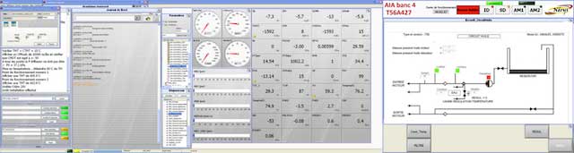
By using VASCO software (Visualize Acquire Supervisor and Control), NERYS was able to propose a quick solution to retrieve all of the supervision data and to control the different valves and pumps. The application runs 24 hours a day, 7 days a week, with the possibility of remote control via an internet explorer.  In addition, when thresholds exceed on certain values, maintenance managers are notified by a text message or a voice server call.  This supervision enables hot water to be supplied to various municipal buildings, including the Judaica swimming pool in Bordeaux.  

AMCPI is responsible for the installation, cabling, project management as well as on-site adjustments.  With this kind of application it is a big plus to have a relay on site just in case there is an evolution and for an efficient after-sales service.

Renovation of a mechanical acyclism bench

Renovation of a mechanical acyclism bench

NERYS a rénové un banc d'essais, d'une mécanique conçue par 01dB-Metravib, permettant de faire de la génération d'acyclisme mécanique.
Ce banc est utilisé pour les tests d'endurance des courroies de distribution chez les constructeurs.

C'est un principe assez simple, le logiciel VASCO pilote les cycles de vitesses à travers une consigne analogique envoyée au variateur. Cela donne une valeur de vitesse, cette dernière est contrôlée à l'aide d'un codeur qui permet d'asservir la régulation de vitesse.
Ensuite on pilote un vérin électrique qui modifie l'angle du cardan, cela à pour effet d'augmenter les vibrations torsionnelles sur l'axe de rotation.

C'est une des toute premières version des moyens d'essais générant de l'acyclisme avec un moteur électrique.
Cela à pour avantage d'être une des moins coûteuses et permet de soumettre les équipements aux principales vibrations qu'ils subiront dans leur utilisation réelle.

Néamoins, on peut reprocher à l'acyclisme mécanique de ne pas être suffisamment configurable et représentatif de la réalité.
On lui préfèrera des moyens de tests plus sophistiqués avec un entrainement direct et un moteur électrique permettant de générer toutes les composantes et leurs harmoniques.

AIA turboshaft Test Rig

AIA turboshaft Test Rig

"The FPGA-based architecture allows us to achieve a high level of reliability and increased flexibility."

- Christian Valade, AIA de Bordeaux

Goal :
Renovating a dated data acquisition and control system for a test cell for turboprop engines while increasing functionality and flexibility.

Solution :
Using the PXI platform with a real-time controller, a PC for test configuration, and a PC for monitoring, with the implementation of the VASCO standard software suite based on LabVIEW software.

Christian Valade - AIA de Bordeaux
Thierry Pugliesi - NÉRYS

Test Cell Number 4 at the Atelier Industriel de l’Aéronautique (AIA) de Bordeaux is used to perform the recondition and repair of turboprop and turboshaft engines used by the French army. Once engines have been repaired, they must be tested to comply with manufacturer specifications.  

Because the test cell was more than 15 years old, the AIA wanted to renovate its data acquisition, control, and system monitoring, and incorporate new features. To do this, the AIA worked with NÉRYS, an NI Alliance Partner. NÉRYS designs and manufactures measurement systems and turnkey test cell systems. The AIA already used NI products in several of its test cells and was looking for an off-the-shelf system. NÉRYS offered a complete solution with the VASCO software suite, based on LabVIEW software. NÉRYS handled the removal of the control system, installation of the new system, and training.

We needed to follow full engine manufacturer test procedures to achieve the main functions required in the specifications. On Test Cell Number 4, engines tested include the Allison T56 used on the Hercules C130 and Hawkeye aircrafts used by the French army. We also tested the AST-600, an auxiliary power unit used on the Atlantique 2 aircraft. The engine was securely mounted on a chassis inside the test cell and a hydraulic brake measures the power output.

Banc d'essais Turbomoteurs à Bordeaux

Figure 1. Turboprop Engine Mounted in Test Cell Number 4

Multiple I/O to Be Measured

We based the data acquisition system for this project on an NI PXI real-time system. The system I/O includes 50 analog inputs (from 10 Hz to 100 Hz), 60 digital inputs, five counter inputs, and a digital channel for serial communication through RS232. We included 10 analog and 45 digital outputs for signal generation. Also, we used 115 calculated channels and 75 operator channels for monitoring and changes during the tests.

The PXI real-time controller drove testing, and we used a Windows PC for monitoring. We dedicated an FPGA module to the control and safety brake. We exported data from the monitoring PC to the AIA general server. A development PC transferred configuration information to the monitoring PC and to the server where the data was saved.

We used a total of three PCs: one workstation for control (for operators), one touch screen computer for control (for adjustments), and one standard PC for monitoring. We describe the functions of these three PCs below.

Banc d'essai

Figure 2. Allison T56 Turboprop Engine


Modular Software Architecture

The VASCO software suite, developed by NÉRYS with LabVIEW, was used for configuration and testing. The standard functionality already met the AIA’s need for an off-the-shelf solution and can be expanded upon by using LabVIEW. The VASCO software suite consisted of configuration (on the development PC), acquisition and remote control (on the PXI real-time controller), test follow up (on the monitoring PC), and data analysis (on any PC). This latter module allowed data post-processing.

We ran the older test plans on PLCs and had to convert them to run in scenario files on the VASCO software. Understanding the full test plan of the turbine engines and their operation was a big part of this project. We had to focus on interacting with the AIA team and understanding the operation of turbine engines and their conduct in the test ranges, and then have them chain into sequences within a scenario.

PXI Real-Time Monitoring and Control

The PXI real-time embedded system distributed the real-time application across the network for precise timing and synchronization. It also included a PXI-7831R FPGA module to manage the brake regulation and the safety of installation. These functions occurred independently of the real-time controller operation and PC monitoring. This architecture achieved a high level of security. In addition, acquisition, generation, control, and safety tasks ran uninterrupted, even if communication was lost with the monitoring PC.

The PXI system software consisted of several main functions: acquisition and signal generation (analog I/O, and logical processing and calculations), two-way communication with the monitoring PC (via Ethernet TCP protocol), management of brake regulation, and safety of installation (mainly via the FPGA). In addition, in case of a communication breakdown with the PC, the PXI front end could automatically attempt to reconnect.

A Development PC for Test Configuration

The development computer enabled the configuration of the entire testing environment through the VASCO configuration module. Some or all of the corresponding files could then transfer to the monitoring PC to prevent unauthorized edits.

We primarily defined a test by engine configuration (type, serial number, type of test pattern report), a configuration of measurement and control channels, operator parameters, and calculated channels (with one or multiple physical channels, operators, or calculated input parameters). The test also included a test scenario (or test plan) with a sequence of procedures described sequentially, which were based on VASCO script functions. The multiple functions completely automate a test. An average of 2,500 lines of basic instructions composed the created scenarios (one per engine).

We could activate the security settings, especially for the brake, through the corresponding VIs (LabVIEW programs files) on the FPGA, on the real-time PXI controller, or on the monitoring PC. When the FPGA or the real-time controller triggered an alarm, the monitoring PC initiated the execution of a specific procedure, depending on the level of the alarm.

A Monitoring PC for Test Control

We used the VASCO test module, which was installed on the monitoring PC, to run the test. The main features of this module included the triggering of communication with the real-time PXI controller and loading the procedures runtime, a data logging module, and human machine interfaces (HMIs).

The standard HMIs for viewing the data were the tachometer, the bar graph, the time and XY graphs, the digital display, and the table. We used other standard HMIs such as the logbook, channel selector, alarm monitor, data recorder, and a general information indicator. We developed some specific views for test management (one per engine) for water systems, oil and fuel, and for the selection and reading of operating points. We display all parameters on the same real-time top page. A menu empowers users to choose among different screen pages.

We use the monitor screen to monitor the progress of automatic procedures, view and comment in the logbook, launch procedures, take measurement points for use in the synthesis of the test reports, and manage the monitoring screens.

The touch screen control makes it easy for both users to simultaneously use two pages of the same application: one using the mouse and the other by touch.

Banc dessais Turbomoteurs Bordeaux3

Figure 3. Human Machine Interfaces for Test Cell Operator Control

An Application That Meets the Needs

We now use the updated test cell as part of normal operations. Regular exchanges with the AIA team and their involvement in the project helped us deliver a tailor-made application that met their exact needs, based on an off-the-shelf solution to control costs. The AIA can now create their own test plans and modify the specific deployment using LabVIEW. The AIA is already working on using this architecture to upgrade the other 10 test cells in the facility that use the VASCO system, and they are working on integrating the system internally.

Author Information:

Thierry Pugliesi

NÉRYS

France

  1480 Avenue d'Arménie
Pôle d'Activités Yvon Morandat
13120 Gardanne

  ZA du Héron
597  route des Bons Prés
73110 La Croix-de-la-Rochette

Conception de moyen d'essais

Your tests partner

Mesulog