Goal :
Renovating a dated data acquisition and control system for a test cell for turboprop engines while increasing functionality and flexibility.
Solution :
Using the PXI platform with a real-time controller, a PC for test configuration, and a PC for monitoring, with the implementation of the VASCO standard software suite based on LabVIEW software.
Christian Valade - AIA de Bordeaux
Thierry Pugliesi - NÉRYS
Test Cell Number 4 at the Atelier Industriel de l’Aéronautique (AIA) de Bordeaux is used to perform the recondition and repair of turboprop and turboshaft engines used by the French army. Once engines have been repaired, they must be tested to comply with manufacturer specifications.
Because the test cell was more than 15 years old, the AIA wanted to renovate its data acquisition, control, and system monitoring, and incorporate new features. To do this, the AIA worked with NÉRYS, an NI Alliance Partner. NÉRYS designs and manufactures measurement systems and turnkey test cell systems. The AIA already used NI products in several of its test cells and was looking for an off-the-shelf system. NÉRYS offered a complete solution with the VASCO software suite, based on LabVIEW software. NÉRYS handled the removal of the control system, installation of the new system, and training.
We needed to follow full engine manufacturer test procedures to achieve the main functions required in the specifications. On Test Cell Number 4, engines tested include the Allison T56 used on the Hercules C130 and Hawkeye aircrafts used by the French army. We also tested the AST-600, an auxiliary power unit used on the Atlantique 2 aircraft. The engine was securely mounted on a chassis inside the test cell and a hydraulic brake measures the power output.

Figure 1. Turboprop Engine Mounted in Test Cell Number 4
Multiple I/O to Be Measured
We based the data acquisition system for this project on an NI PXI real-time system. The system I/O includes 50 analog inputs (from 10 Hz to 100 Hz), 60 digital inputs, five counter inputs, and a digital channel for serial communication through RS232. We included 10 analog and 45 digital outputs for signal generation. Also, we used 115 calculated channels and 75 operator channels for monitoring and changes during the tests.
The PXI real-time controller drove testing, and we used a Windows PC for monitoring. We dedicated an FPGA module to the control and safety brake. We exported data from the monitoring PC to the AIA general server. A development PC transferred configuration information to the monitoring PC and to the server where the data was saved.
We used a total of three PCs: one workstation for control (for operators), one touch screen computer for control (for adjustments), and one standard PC for monitoring. We describe the functions of these three PCs below.

Figure 2. Allison T56 Turboprop Engine
Modular Software Architecture
The VASCO software suite, developed by NÉRYS with LabVIEW, was used for configuration and testing. The standard functionality already met the AIA’s need for an off-the-shelf solution and can be expanded upon by using LabVIEW. The VASCO software suite consisted of configuration (on the development PC), acquisition and remote control (on the PXI real-time controller), test follow up (on the monitoring PC), and data analysis (on any PC). This latter module allowed data post-processing.
We ran the older test plans on PLCs and had to convert them to run in scenario files on the VASCO software. Understanding the full test plan of the turbine engines and their operation was a big part of this project. We had to focus on interacting with the AIA team and understanding the operation of turbine engines and their conduct in the test ranges, and then have them chain into sequences within a scenario.
PXI Real-Time Monitoring and Control
The PXI real-time embedded system distributed the real-time application across the network for precise timing and synchronization. It also included a PXI-7831R FPGA module to manage the brake regulation and the safety of installation. These functions occurred independently of the real-time controller operation and PC monitoring. This architecture achieved a high level of security. In addition, acquisition, generation, control, and safety tasks ran uninterrupted, even if communication was lost with the monitoring PC.
The PXI system software consisted of several main functions: acquisition and signal generation (analog I/O, and logical processing and calculations), two-way communication with the monitoring PC (via Ethernet TCP protocol), management of brake regulation, and safety of installation (mainly via the FPGA). In addition, in case of a communication breakdown with the PC, the PXI front end could automatically attempt to reconnect.
A Development PC for Test Configuration
The development computer enabled the configuration of the entire testing environment through the VASCO configuration module. Some or all of the corresponding files could then transfer to the monitoring PC to prevent unauthorized edits.
We primarily defined a test by engine configuration (type, serial number, type of test pattern report), a configuration of measurement and control channels, operator parameters, and calculated channels (with one or multiple physical channels, operators, or calculated input parameters). The test also included a test scenario (or test plan) with a sequence of procedures described sequentially, which were based on VASCO script functions. The multiple functions completely automate a test. An average of 2,500 lines of basic instructions composed the created scenarios (one per engine).
We could activate the security settings, especially for the brake, through the corresponding VIs (LabVIEW programs files) on the FPGA, on the real-time PXI controller, or on the monitoring PC. When the FPGA or the real-time controller triggered an alarm, the monitoring PC initiated the execution of a specific procedure, depending on the level of the alarm.
A Monitoring PC for Test Control
We used the VASCO test module, which was installed on the monitoring PC, to run the test. The main features of this module included the triggering of communication with the real-time PXI controller and loading the procedures runtime, a data logging module, and human machine interfaces (HMIs).
The standard HMIs for viewing the data were the tachometer, the bar graph, the time and XY graphs, the digital display, and the table. We used other standard HMIs such as the logbook, channel selector, alarm monitor, data recorder, and a general information indicator. We developed some specific views for test management (one per engine) for water systems, oil and fuel, and for the selection and reading of operating points. We display all parameters on the same real-time top page. A menu empowers users to choose among different screen pages.
We use the monitor screen to monitor the progress of automatic procedures, view and comment in the logbook, launch procedures, take measurement points for use in the synthesis of the test reports, and manage the monitoring screens.
The touch screen control makes it easy for both users to simultaneously use two pages of the same application: one using the mouse and the other by touch.
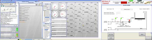
Figure 3. Human Machine Interfaces for Test Cell Operator Control
An Application That Meets the Needs
We now use the updated test cell as part of normal operations. Regular exchanges with the AIA team and their involvement in the project helped us deliver a tailor-made application that met their exact needs, based on an off-the-shelf solution to control costs. The AIA can now create their own test plans and modify the specific deployment using LabVIEW. The AIA is already working on using this architecture to upgrade the other 10 test cells in the facility that use the VASCO system, and they are working on integrating the system internally.
Author Information:
Thierry Pugliesi
NÉRYS
France


